IMU
IMU measures and informs about velocity, attitude and forces by combining the accelerometer and gyroscope readings.
Veronte Autopilot 1x needs to receive 7 measurements: 3-axis accelerometer, 3-axis gyroscope and sensor device temperature.
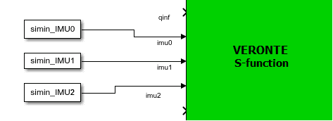
In the S-Function there are 3 inputs for IMUs. These IMUs are mounted differently on the Autopilot 1x (they may not be aligned with the autopilot), so the user has to keep in mind the rotation matrix that the Autopilot 1x is using.
Important
The rotation matrices listed in the following table are the required rotations between each sensor and the Autopilot 1x board coordinates (for more information on Veronte Autopilot 1x coordinates, please check the Orientation - Hardware Installation section of the 1x Hardware Manual).
There may be inputs (ports) not connected since the S-Function contains the maximum number of possible inputs for the different hardware versions, as can be seen in the following table.
As detailed in the table below, if users wish to enter measurements for IMU 3 of hardware version
4.8, they must enter them into the IMU 1 input of SIL S-Function.This is because the block input values belonging to IMU 1 also go internally to this IMU. Therefore, the same S-Function can be used for both version
4.0and4.8.
Hardware version |
S-Function Input |
Rotation Matrix |
1x PDI Builder equivalence |
|
|---|---|---|---|---|
PIN |
Description |
|||
4.0 |
5 |
IMU 1 |
\(R =\begin{pmatrix} 0 & 1 & 0 \\ 1 & 0 & 0 \\ 0 & 0 & -1 \end{pmatrix}\) |
0 - Internal 0 |
6 |
IMU 2 |
\(R =\begin{pmatrix} 0 & 0 & -1 \\ 1 & 0 & 0 \\ 0 & -1 & 0 \end{pmatrix}\) |
1 - Internal 1 |
|
4.5 |
5 |
IMU 1 |
\(R =\begin{pmatrix} 0 & 1 & 0 \\ 1 & 0 & 0 \\ 0 & 0 & -1 \end{pmatrix}\) |
0 - Internal 0 |
6 |
IMU 2 |
\(R =\begin{pmatrix} 0 & 0 & -1 \\ 1 & 0 & 0 \\ 0 & -1 & 0 \end{pmatrix}\) |
1 - Internal 1 |
|
7 |
IMU 3 |
\(R =\begin{pmatrix} 0 & -1 & 0 \\ -1 & 0 & 0 \\ 0 & 0 & -1 \end{pmatrix}\) |
2 - Internal 2 |
|
4.8 |
5 |
IMU 1 |
\(R =\begin{pmatrix} 1 & 0 & 0 \\ 0 & 0 & 1 \\ 0 & -1 & 0 \end{pmatrix}\) |
3 - Internal 3 Note Internal 3 corresponds to IMU 1 S-Function Input as explained in the previous note |
6 |
IMU 2 |
\(R =\begin{pmatrix} -1 & 0 & 0 \\ 0 & 0 & 1 \\ 0 & 1 & 0 \end{pmatrix}\) |
1 - Internal 1 |
|
7 |
IMU 3 |
\(R =\begin{pmatrix} -1 & 0 & 0 \\ 0 & 0 & 1 \\ 0 & 1 & 0 \end{pmatrix}\) |
2 - Internal 2 |
|
Within the S-Function, the introduced data is transformed to match the coordinates of Veronte Autopilot 1x. So, in order to be correctly transformed inside the S-Function, the data must have been previously “prepared” to be introduced into it in the following way:
In the example provided by Embention with the SIL package, the simin_IMU0 block already has this transformation implemented, so it can be entered directly into the S-Function without prior “preparation”.
There are several ways to implement a suitable read group for an IMU:
Constant value
The user can create a vector with constant values.
From Workspace block
Another option could be to store some data (i.e. from a previous flight), load it into the matlab workspace, and then send these values to Simulink using the block name as From Workspace.
IMU - From workspace blocks
This block allows the user to read from an array of values (and interpolate when there is no information in this step). Moreover, users can choose between several options in case data vector is over. For example, it is possible to extrapolate the information or reset the list of values.
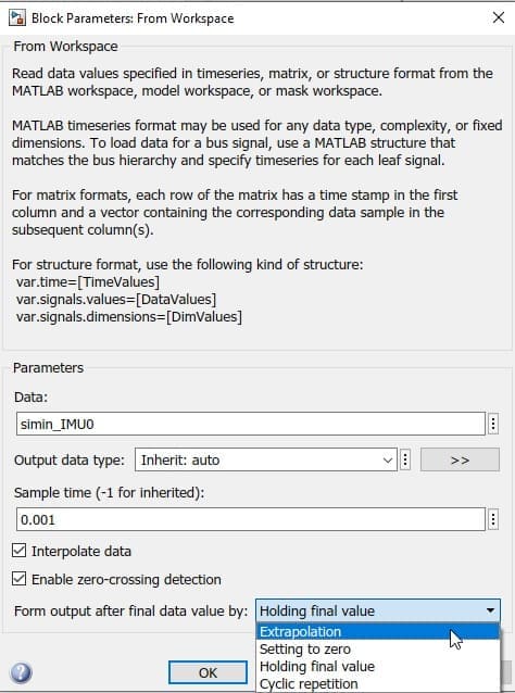
From workspace block configuration
Complex model
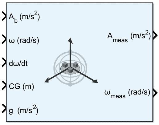
Another method is to read these values from Environment (gravity vector in NED frame and air temperature) and from States (acceleration in body axes, angular velocity, angular acceleration and the rotation matrix from NED to Body).
These values are fed into a Matlab function in which the IMU behavior is simulated and the measurements are computed. In addition, users have to cross-reference the measurements or apply a rotation matrix depending on the orientation of the IMU sensor.
In the example below, this data feeds the first port (this IMU is selected in the 1x PDI Builder configuration). Therefore, the user has to cross the signals to adjust the rotation matrix.
The complete subsystem results as follows:
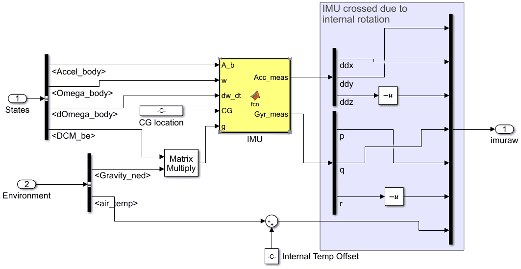
IMU - Subsystem
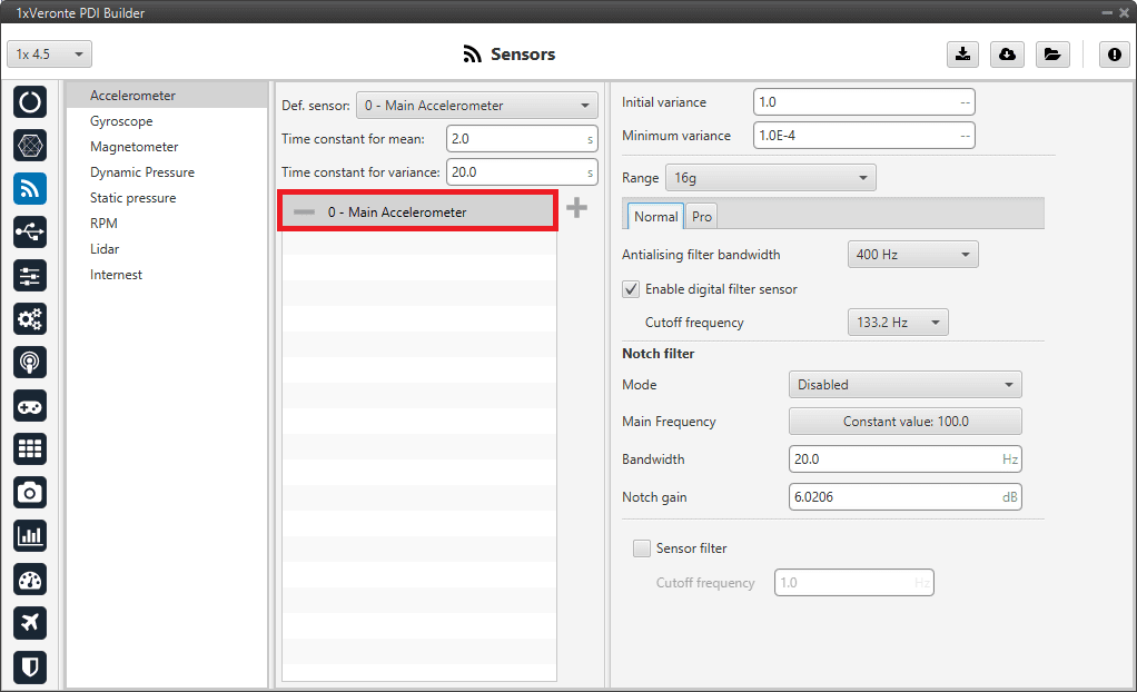
IMU - Accelerometer selected in 1x PDI Builder
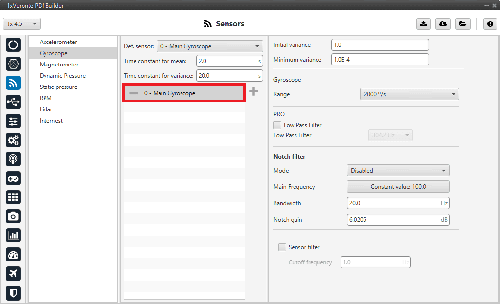
IMU - Gyroscope selected in 1x PDI Builder
However, instead of using a user function, Aerospace blockset includes some functions for IMU simulation that can be employed:
IMU - Aerospace Toolbox block
Specific example from the example provided by Embention
The data of the provided example are already prepared to be introduced in the IMU 1 input of the S-Function, this is because it corresponds to the IMU 0 sensor in hardware version
4.0.Therefore, if users want to use the data provided by Embention (simin_IMU0) and in their PDI configuration they have selected the IMU 3 with hardware version
4.8, the following transformations are necessary for correct operation:Transform from IMU 0 to board coordinates
Undo the “preparation for input” (this “preparation” has been described at the beginning of the section) to obtain the data provided by the sensor in body coordinates:
\[\begin{split}data_{(board)} = \begin{pmatrix} 0 & 1 & 0 \\ 1 & 0 & 0 \\ 0 & 0 & -1 \end{pmatrix} \cdot data_{(example)}\end{split}\]\(data_{(example)}\) is the data inside the simin_IMU0 block
Transform from board to IMU 3 coordinates
Prepare the data for conversion to IMU 3 coordinates by multiplying the sensor body data by the IMU 3 rotation matrix transpose:
\[\begin{split}data_{(input)} = \begin{pmatrix} 1 & 0 & 0 \\ 0 & 0 & -1 \\ 0 & 1 & 0 \end{pmatrix} \cdot data_{(board)}\end{split}\]
Finally, the whole transformation should look like this:
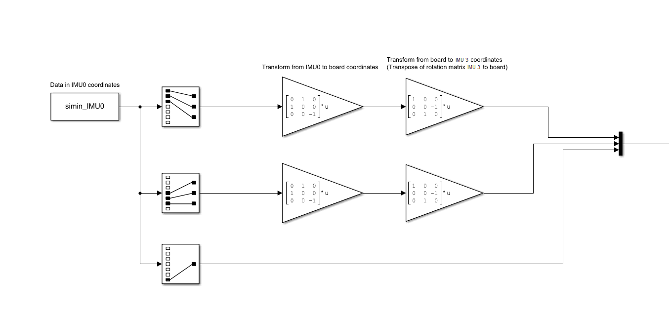
IMU - Example